

Set intermediate posts no more than 3 feet on center, and stretch to 48 inches only where the manufacturer's tested assembly says that span is allowed. Either way, the gaps between cables have to stay tight enough that a 4-inch sphere can't pass through, and post spacing is the variable that decides it under load.
Cable railing sells the view. Thin horizontal lines, an open horizon, no pickets chopping up the scene. It looks effortless from the deck. Then someone leans on the middle of a long run and the cables part like a fan, and the effortless look turns into a callback.
The part responsible is the one nobody photographs. An intermediate post is the short vertical member standing between the end posts and corner posts, holding each unsupported cable span down to a length that resists a hand. Where those posts land decides whether the finished guard keeps a sphere out under pressure, how the top rail behaves when a body leans on it, and whether an inspector signs the job or asks for a rebuild.
The forces aren't cosmetic. A tensioned cable pushes sideways on every post it passes through, and an end post collects that push from every cable in the run. Get the rhythm right and the railing looks delicate while acting like a fence. Get it wrong and no amount of cable tension rescues it.
What follows is the spacing table you can mark on a framing plan, the two separate jobs these posts do, an install sequence that finishes with a load test, and the adjustments that long runs, corners, stairs and commercial occupancies demand.
Table of Contents
- Why Intermediate Posts Make or Break a Cable Railing
- Intermediate Post Spacing at a Glance
- What Intermediate Posts Do and the Mistakes That Undo Them
- How to Install Intermediate Posts Step by Step
- Spacing for Long Runs, Corners, and Stairs
- Jurisdiction Check and Project Spacing Worksheet
- Plan Your Intermediate Posts With Confidence
Why Intermediate Posts Make or Break a Cable Railing
A long cable bay fails in the middle, not at the hardware. Push the center of an unsupported span and the lines bow apart until the opening is wider than a fist. The cable is still tensioned. The span is too long for that tension to hold the gap shut.
Intermediate posts shorten the distance a cable can travel sideways. Add one to a bay and a push at midspan has less cable to bow and less room to open a hole. Remove one and the same cable that felt solid acts like a hinge.
The stakes are legal as much as physical. Guard rules generally prohibit a 4-inch-diameter sphere from passing through any opening in the completed assembly, and a cable-infilled guard is judged as a whole, not as a drawing. Posts set too far apart let cables bow past that limit. The remedy afterward is a rebuild, not a wrench.
Two jobs sit on that spacing, and they are not the same job.
Deflection control comes first. The intermediate member keeps each cable from spreading under a hand. It interrupts the span so the opening stays closed. It does not have to collect the full pull of every cable in the run.
The structural load path is separate. The top rail has to hold its line under load, and that load has to reach the deck framing rather than stopping at a post base. End posts, and intermediates specified as structural, carry the rail and the sideways force in the cables. A spacer that only limits deflection does not.
I would not swap those roles on a guess. Use a full structural post wherever the rail must deliver load into the frame. Use a spacer only where two posts already carry the run and the remaining problem is cable bow. Check the local code, and the tested assembly, before ordering hardware.
The order below is the order to work in: the spacing numbers and where each comes from, the split between a load-carrying post and a deflection spacer, the installation sequence, then the adjustments for long runs, corners, stairs, and public buildings.
Intermediate Post Spacing at a Glance
A 36-inch on-center interval is a practical starting point for intermediate posts. A 48-inch interval is appropriate only when the manufacturer's tested assembly permits it. Keep each measurement on the same reference line so the layout stays consistent and cable fittings align.
| Element | Working limit | Why it matters |
|---|---|---|
| Main end and corner posts | Set according to the system design and supporting structure | Anchor the run and resist cable tension |
| Intermediate posts | 36 in on center as a working default; up to 48 in only in tested systems | Limit cable deflection and help keep openings within the guard limit |
| Cable spacing | About 3 in on center | Leaves room for deflection below the 4 in sphere limit |
| Guard opening | 4 in sphere must not pass | IRC and IBC infill rule that governs the completed guard |
| Top rail load | 200 lb concentrated load | Posts and connections must transfer the required load |
| Cable tension | Determined by the railing system | End and corner posts resist the accumulated cable pull |
How Each Row Earns Its Number
The main end and corner posts carry the accumulated pull of the cables. Their spacing depends on the system design and the structure supporting them, so a generic six-foot rule is not a reliable specification.
For intermediate posts, the Feeney white paper on installing deck posts for cable railings discusses cable support intervals up to 48 inches. Use that wider interval only when the tested assembly covers it. Otherwise, 36 inches on center is a conservative working default.
Cable spacing and post spacing solve different problems. Cable lines at about 3 inches on center leave room for deflection below the 4-inch sphere limit; intermediate posts limit how far the cables can bow between supports. The IRC's 200-pound concentrated load applies to the guard, and the posts and their connections must transfer that load into the supporting structure.
Three Rules for Using the Table
Follow the tested assembly. Use the manufacturer's published maximum interval, which may be shorter for a particular configuration.
Use 36 inches when system documentation gives no spacing limit. A tighter interval reduces the unsupported cable span and leaves less room for deflection.
Check the local code before ordering hardware. The jurisdiction's requirements and the tested system both shape the final layout.
Working rule: If the system documentation does not specify a tested maximum, use 3 feet between intermediate posts and confirm the layout with the local code authority.
Use these figures to sketch the post layout, then confirm the selected spacing against the railing system and the project's code requirements.
What Intermediate Posts Do and the Mistakes That Undo Them
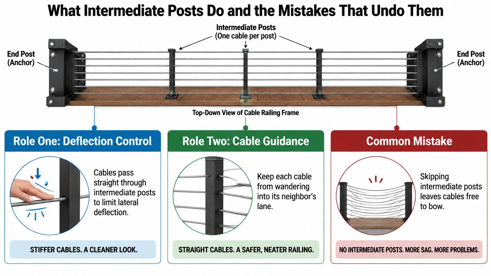
A cable run works like a tug-of-war with two different players. End and corner posts are the anchors. They take the pull of every cable at once. Intermediate posts are not pulling. They stand in the span and hold each strand in its lane so a lean cannot walk the cables sideways into an opening that fails inspection.
That split decides hardware, fasteners, and cost. Call both members the same post and you either overbuild spacers or underbuild the posts that carry load.
Two Jobs That Get Treated as One
Deflection control is the first job. Cables pass through guides in the intermediate post, so the member carries almost none of the tension in a continuous run. Its value is geometric. A shorter unsupported span bows less when someone pushes. JLC's cable rail mistake breakdown draws the same line: intermediate posts or pickets may carry minimal cable-tension loads when cables pass through continuously, while the primary structural requirement is supporting the top rail and transferring code-required lateral loads into the deck or stair structure.
Structural support is the second job. A member that carries the handrail has to hold that rail in line under a lean and hand the load to framing that can take it. A thin spacer that only limits cable travel is not the same component as a post holding a top rail, even when both stand the same distance apart. Treating "a post every few feet" as one rule skips that difference.
The Three-Question Test for a Full Structural Post
Before you order, run each member through three questions. Does it support the handrail? Does it terminate a cable run? Does it resist code-required lateral loads?
Any yes means a full structural post with real blocking and rated fasteners. All no means the member is pure deflection control. On some systems a slimmer vertical spacer or cable brace does that work without the footprint of a structural post. I order the structural post wherever one of those answers is yes, and I spend the lighter hardware only on members that never see the handrail or a cable termination.
Read the load path the same way. The assembly shares the work. Every fastener between the rail and the deck joist is part of the route from a lean to the framing. A spacer that never joins that path does not get credit for it.
Mistakes That Undo a Good Layout
Tight cable spacing does not finish the job by itself. Cables set near 3 inches on center can still spread enough that a 4-inch sphere passes if a long unsupported span lets them deflect, which is the opening check in a code-oriented spacing guide from Utah Deck Supply.
Extra intermediate posts will not rescue undersized end posts, weak fasteners, or springy framing. If the anchors move, every cable in the run goes slack at once.
More tension is the wrong substitute for a shorter span. Cranking the cables reduces sag and dumps more load into the terminal posts and their connections. You trade a deflection problem for an anchor problem.
One published interval does not travel from job to job. Some layouts allow a wider support spacing along the cable. Others call for a shorter one. Either way, the lateral load still has to reach solid framing. Match the interval to the system in hand and to the member's job, not to a number that worked on the last deck.
Intermediate posts are not decoration. They are structural, or they are deflection control. Leave either job unfinished and the railing looks done until someone leans on it. Inspection reads the finished assembly, including the gaps near the deck, the posts, and the handrail, not the year printed on a code book.
How to Install Intermediate Posts Step by Step
I split intermediate posts into two jobs before marking a single centerline. A deflection spacer only keeps the cables from opening between structural posts. A structural post has to put the cumulative cable tension into blocking that does not move. If a spacer is asked to do the second job, the run will look tight on day one and go slack once the anchors shift.
The sequence below assumes the layout is already decided. Where post bases land relative to blocking matters just as much as the spacing itself, and the deck railing post installation guide covers the base-to-frame details that this sequence skips. Read that first if you're mounting to an existing deck rather than new framing.
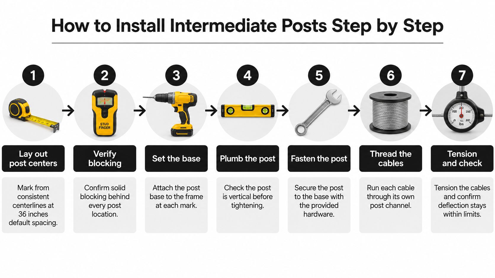
1. Lay out the centers. Default to 36 inches, measured from consistent centerlines rather than from the edge of a deck board. The common slip is measuring the first bay from the fascia and the next from a post face, which puts every subsequent hole off by the width of one board. Mark structural posts and cable spacers as two different symbols so a spacer never lands where the frame needs a real anchor.
2. Verify blocking before you drill. For surface mount railings, reinforced blocking is required, commonly triple 2x8 or equivalent. For side mount railings, solid backing is required, commonly double 2x8 or equivalent. The slip here is trusting a stud finder on an old deck. Pull a board or drill a test hole and confirm what is behind the fascia. A spacer can use lighter backing only when the manufacturer designed it that way. End posts and corners still need the full structural path.
3. Fasten the post plumb. Through-bolts or the manufacturer's specified screws into that blocking, never into deck boards alone. Shimming a base until the post looks upright is not plumbing it, and a post that leans out shows up as slack cable six months later.
4. Confirm height from the right reference. Measure from the mounting surface to the top of the handrail, not just the post. A post at the correct height with the wrong bracket stack still lands the rail at the wrong elevation, and 36-inch or 42-inch systems only work when the full assembly adds up.
5. Run the cables. Thread each strand through its own guide in the intermediate post at the cable spacing the system specifies, keeping the holes aligned so the cable travels straight. A single misaligned guide binds the strand and drags tension readings out of range. On a spacer, that hole is a guide. It is not a termination.
6. Tension incrementally and evenly. Field guidance puts cable tension at roughly 200–300 lbf per cable, with the end posts receiving the cumulative horizontal force from every tensioned cable, per metal railing fabrication guidance from Anvil Field. A wider bay belongs only on an assembly the manufacturer has already tested for that span. Over-tensioning to stiffen a weak frame is the most common error on this step. Extra pull does not turn a spacer into a structural post.
7. Test the finished guard under load. Press on the cables and the rail at several points along the run and confirm no opening passes a 4-inch sphere. Do it before the inspector does, because the fix at that stage is a tension adjustment or an added post, while the fix after a failed inspection includes a schedule.
A video walkthrough helps if you want to see the same sequence in motion before committing to a layout.
Spacing for Long Runs, Corners, and Stairs
The 36-inch default is a starting point, not a plan. Run length, corners, slope and occupancy all push the spacing tighter, and the table below is the adjustment layer I'd apply on top of that default before ordering a single fitting.
| Run type | Intermediate support spacing | Additional considerations |
|---|---|---|
| Straight residential run | 36–48 in, 36 in for conservative control | Keep total run length to about 70 ft |
| Run with corners or turns | Tighter spacing near each corner | Cap runs with turns at about 40 ft; corners act as tension points |
| Stair run | Maintain the rhythm along the slope | Verify openings on the angled plane; use stair-specific hardware |
| Long commercial or hospitality run | 36 in default; divide with intermediate termination posts if needed | Easier tensioning access and maintenance on long runs |
| High-use public area | 36 in default; 48 in only with engineering | Verify local code; heavier public use demands stricter assumptions |
Where Straight Runs Run Out
Long straight lengths can fail without warning. Tensioning gets harder to balance from one end, the cable takes up stretch unevenly, and deflection at midspan grows with distance. Installation guidance from Feeney recommends limiting straight cable runs to about 70 feet and runs with turns to about 40 feet, since every bend and longer span complicates tensioning and deflection control. That same guidance allows cable support intervals no greater than 48 inches in some designs, which is exactly why you can't lift a spacing number from one project and apply it to another.
Corners, Stairs, and the Termination Question
Corners behave like anchors, so treat them as tension points rather than decoration. A corner post absorbs a change in direction, and the bays on either side of it usually need tightening. If you're still deciding how corners get framed, this corner post for deck railing breakdown walks through the offset and double-post options.
Stairs add a geometry problem on top of the tension problem. Keep the post rhythm consistent along the slope so the railing doesn't look crowded at the bottom and sparse at the top, then check openings on the angled plane rather than the horizontal one, because load direction and gravity change where deflection shows up.
Long commercial and hospitality runs force a choice. Intermediate termination posts cost more hardware and more drilling, but they break the run into tuneable segments and make future maintenance a one-bay job. Continuous cable through intermediate members looks cleaner and is harder to retension when one strand goes slack.
For public areas, the residential default is too loose. Hospitality and heavy-foot-traffic projects should assume 36 inches, treat 48 as an engineered exception, and expect the building department to say so first.
Jurisdiction Check and Project Spacing Worksheet
Every number in this guide is a starting point until the local building department agrees with it. The Feeney installation document warns that manufacturer recommendations may not comply with every state, county, or city code, and that warning is the most useful line in the whole file. Build a worksheet for each project and fill it before the purchase order goes out.
- Record the run inputs. Total straight length, number and angle of each corner, stair slope, and occupancy. Private residential, hospitality, and public guard each carry different assumptions.
- Pull the tested assembly. Note the manufacturer's maximum intermediate interval, plus any stair-specific or corner-specific rules, and attach the page to the worksheet so nobody argues with memory later.
- Ask the building department how it reads cable infill. Call, don't email, and ask whether the jurisdiction applies any local amendment to the sphere rule or restricts horizontal cable near grade.
- Write down the governing spacing. Use the tighter of the manufacturer's tested interval and the local interpretation, and note where you tightened further at corners or on stairs.
- Decide termination versus continuous cable. Any run beyond roughly 70 feet, or with turns beyond about 40 feet, deserves the termination question answered on paper rather than in the field.
- Add a sign-off line. Installer initials and inspector initials on the same sheet. That sheet becomes the spacing plan behind the hardware order and the record you want if a cable goes slack two seasons later.
Two references shorten the research. The cable railing code requirements guide summarizes the guard rules that come up in inspection, and our own Cable Railing Safety Code page on the Ultra Modern Rails site collects the same material in one place, which is useful when a client asks why a wider span isn't allowed.
Inspection habit: photograph the worksheet next to the finished run. It costs ten seconds and settles most disputes about what was specified.
Plan Your Intermediate Posts With Confidence
Everything above reduces to five decisions. Make them in order and the hardware order takes care of itself.
- Confirm the governing code with the local building department before you buy anything. A phone call is cheaper than a rejected inspection.
- Choose a tested system and follow its spacing. 36 inches is the dependable default; 48 inches applies only where engineering and testing support it.
- Plan the load path end to end. Correctly sized end and corner posts, blocking rated for the pull, and the specified fasteners. Ultra Modern Rails kits are IRC and IBC compliant and meet residential and commercial code, but compliance assumes the frame behind them holds up.
- Match the rhythm to the run type. Tighten assumptions at corners, on stairs, and anywhere the public leans on the rail.
- Verify openings under load before you call it finished. Push, measure, then sign off.
The single decision that saves the most rework is locking the spacing plan first and ordering hardware to match it. Doing it the other way around means a box of fittings that force a layout you never wanted.
For a custom layout, Ultra Modern Rails supplies factory-direct stainless steel cable railing systems for decks, balconies, stairs and commercial spaces. Send your measurements, corner angles, stair slope and occupancy, and you'll get a professional review of the spacing before anything ships.
Ultra Modern Rails builds factory-direct stainless steel cable railing systems for decks, balconies, stairs and commercial runs, with every kit engineered to IRC and IBC requirements for residential and commercial use. If this guide settled your spacing questions but left you sizing posts, handrails and mounting styles, send the run details and we'll turn them into a drawing you can install from. Visit Ultra Modern Rails for a free custom quote and drawing within 24 hours.