

A stainless steel cable grip isn't automatically a safe cable end just because it's made of stainless steel. The material can resist corrosion, but the grip's load capacity depends on its size, its fit on the rope, and the job it's expected to do. A clamp that works for adjusting a railing cable may be unsuitable as a permanent structural termination, and a corrosion-resistant part can still slip, wear, or fail.
Start with the cable's actual diameter, the load path, and the environment. Then check the grip's rating and installation instructions. Those details matter more than the word “stainless.”
Table of Contents
- What a Stainless Steel Cable Grip Does
- Working Load Limits by Cable Diameter
- Matching the Stainless Grade to Your Environment
- How Corrosion and Bending Shorten Cable Life
- When a Grip Is the Wrong Termination
- Fit, Verify and Inspect the Grip
What a Stainless Steel Cable Grip Does
A stainless steel cable grip is a clamp that holds wire rope under tension at a fixed point. On a railing, you can picture three parts working together: the stainless wire rope, the grip body, and an anchor point on a post or fitting. A standard clamp has a saddle and U-bolt; a braided cable grip uses a wire-mesh body that tightens around the rope.
The clamp holds the cable at the anchor. Depending on the design, it may also be loosened and retightened to adjust the run. That adjustability is useful during installation, but it doesn't make every grip appropriate as a permanent, load-bearing termination.
The rope itself is made of wires twisted into strands, with the strands wound around a core. A common 7 × 19 construction has seven strands of 19 wires each, or 133 wires before accounting for the core arrangement. Like many thin threads twisted into one yarn, the construction lets the rope bend while retaining strength. The technical paper on stainless-steel wire rope construction describes how this wire-rope architecture contributes to flexibility and makes the rope useful in exposed applications such as railings and marine equipment.
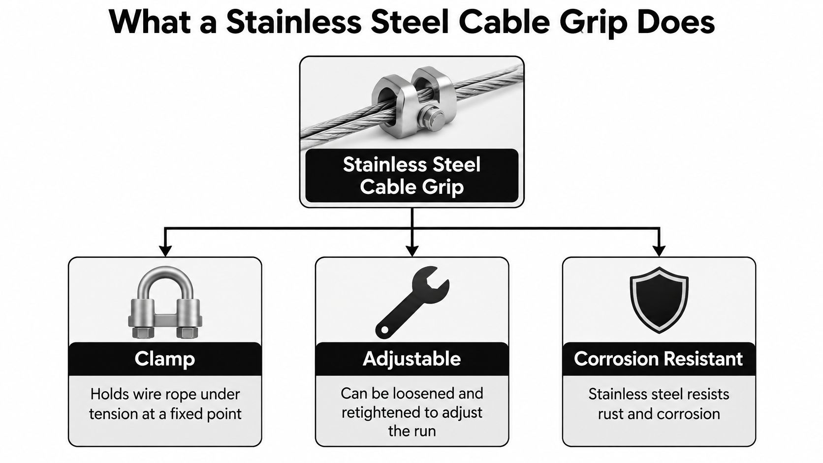
A grip isn't the same as a swaged or welded fitting. Those fittings are made to create a permanent connection, while an adjustable grip can be released and reset. The name “stainless steel cable grip” tells you about the material and general function, not the load rating or suitability for a particular structure.
Read the label as a set of matching details: rope construction, the cable diameter the grip is sized for, and the wire grade. If any of these is missing, don't guess.
Working Load Limits by Cable Diameter
| Cable outside diameter (in) | Working-load limit (lb) |
|---|---|
| 0.50–0.61 | 75 |
| 0.63–0.75 | 115 |
| 1.00–1.24 | 190 |
| 1.25–1.49 | 445 |
| 2.00–2.49 | 890 |
These are published CSA-certified examples of working-load limits for stainless steel cable grips, listed by cable diameter in the manufacturer's cable-support grip specifications. The rating is tied to the grip's mesh geometry and the cable's actual outside diameter, not to the material or the rope's breaking strength.
Use the table as a matching tool, not as a complete design. A grip must fit the cable's measured diameter, and its working-load limit must exceed the service load after applying the project's required safety factor. A diameter that falls between the listed ranges isn't covered by these examples. Use the manufacturer's product sheet to identify the correct size and rating.
Measure first, then check the load
- Measure the cable. Use calipers on a clean, straight section. Don't rely only on the nominal size printed on the spool.
- Match the measured diameter to a listed range. The cable must fall within the grip's stated range.
- Read the working-load limit. Don't substitute the cable's tensile or breaking strength for the grip's rating.
- Compare the rating with the design load. Multiply the calculated service load by the project safety factor, then confirm the grip's working-load limit exceeds that result.
For example, suppose a 0.50-inch cable carries a calculated service load of 40 lb, and the project uses an assumed safety factor of 2. The required limit is 80 lb. The listed grip for 0.50–0.61-inch cable has a 75 lb working-load limit, so it doesn't meet that example's requirement. The answer isn't to tighten it harder. Choose a different termination or have an engineer review the design.
A grip that's too small may damage the rope or fail to engage fully. One that's too large can have less mesh contact and reduced holding efficiency.
Leave space for the hardware before cutting the cable. Overall grip lengths in the published examples range from approximately 17 to 37 inches, so check the product drawing for clearance and the tail length needed at the termination. For general sizing context, compare the grip range with the stainless steel cable size guide.
Matching the Stainless Grade to Your Environment
Treat stainless grade and load capacity as separate checks. Grade selection affects how the grip withstands its exposure, while the listed working-load limit determines whether the termination can carry the required load. A higher-alloy grip should not be assumed to be a stronger or universal termination.
| Environment | Recommended grade | What to watch |
|---|---|---|
| Dry interior or sheltered deck | 304 | Adequate while salt and chlorine stay away from the grip |
| Outdoor deck or balcony exposed to rain | 304 or 316 | 316 for longer life in damp, humid climates |
| Coastal or salt-spray site | 316 or 316LN | 316 can still pit in chloride; plan drainage and inspection |
| Pool deck or chlorinated area | 316 or 316LN | Chloride exposure; rinse and inspect on a schedule |
| De-icing salt road or walkway | 316 or 316LN | Salt deposits can trap moisture in crevices |
| Chemically contaminated industrial site | Confirm with supplier | Check the grade against the supplier's corrosion data |
Stainless steel resists corrosion; it does not eliminate it. Chlorides in sea spray, pool water, de-icing salt, and coastal air can attack stainless steel, especially where moisture and salt remain trapped against the surface. A sheltered interior and a salt-spray coastline may use the same cable diameter, but they place very different demands on the grip.
In a 2023 study of AISI 316 mooring ropes in tropical seawater, all three tested ropes showed hollow-wire corrosion, and the most damaged rope had been in service for only a few months. The finding shows that a corrosion-resistant grade can still deteriorate quickly under sustained exposure.
Grade comparisons also have limits. Corrosion performance depends on test conditions and actual exposure, so a higher-alloy grade is not automatically the right choice for every site. A chloride environment calls for greater corrosion resistance than a dry interior, but no grade removes the need to control water and salt.
A grip can still corrode where water sits in a crevice, around a fitting, or between the mesh and the rope. Keep the assembly clean, allow water to drain, and set an inspection schedule that suits the exposure. For a contaminated industrial site, compare the proposed alloy with the supplier's corrosion information for the chemicals present. The guide to stainless-steel and steel corrosion explains how different exposure conditions change corrosion risk.
How Corrosion and Bending Shorten Cable Life
Corrosion pits act as stress points, and repeated bending can drive cracks from them, so a stainless rope may fail sooner than its alloy name suggests. Damage often begins where water or salt can collect, then grows as the cable flexes under load.
In a failure analysis of AISI 304 7 × 19 wire rope, investigators found corrosion debris enriched with oxygen and chlorine on the rope's perimeter and fracture surface. The reported failure mode was intergranular fracture associated with corrosive exposure. Separate corrosion-fatigue testing found that the fatigue life of a 6 × 36 Warrington-Seale rope decreased as corrosion exposure increased. At a sheave-to-rope diameter ratio of 25, fatigue life fell 30.4% when tensile load rose from 11.7 to 17.0 kN, according to the wire-rope failure analysis and corrosion-fatigue findings.
That combination matters in moving systems, where the rope repeatedly bends around a sheave or pulley. It also matters in a railing or support where vibration, movement, or tension changes repeatedly work on a damaged area. Corrosion pits concentrate stress; bending adds cycles that can extend cracks.
Inspect the rope and grip together
Walk the cable run and check both the grip and the section of rope where it exits the grip. Look for:
- Broken wires: Replace a rope with broken wires rather than retightening the grip.
- Discoloration or rust trails: Check for trapped moisture, salt, or contamination.
- Pitting: Treat visible pits as damage, not just surface staining.
- Grip slippage: Look for a change in position or cable tension.
- Repeated bending: Check where the rope passes over or around fittings for wear.
Keep loads and bend radii within the design requirements, and limit unnecessary movement. Make inspections routine: walk the run, examine the termination and the rope beside it, then record changes so gradual damage doesn't go unnoticed.
When a Grip Is the Wrong Termination
Stainless steel describes corrosion resistance. It doesn't establish a grip's allowable load or prove that the connection is suitable for a structural railing. A grip may hold a cable for adjustment but still be the wrong choice as the primary load-bearing connection.
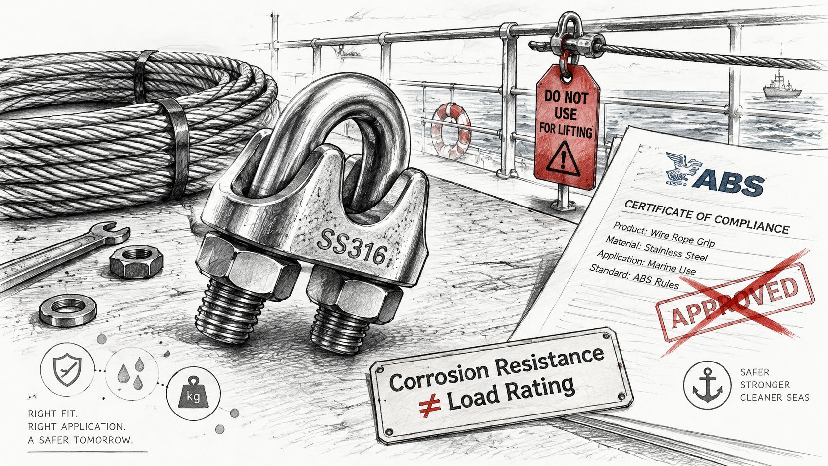
Start by asking what role the termination plays. Is it for a non-load-bearing adjustment, or is it a permanent connection in the load path? Is the cable part of architectural railing, or does it support lifting, a suspended load, or a fall-arrest system? And is the assembly tested as a complete system, or is it a generic clamp chosen because it fits?
| Application | Load role | Grip suitability |
|---|---|---|
| Decorative cable railing on a deck or balcony | Guard infill, static load | Suitable when diameter, rating, and torque follow the manufacturer |
| Adjusting tension on a railing run | Non-load-bearing adjustment | Suitable for adjustment, not as a permanent structural anchor |
| Permanent termination on a tension-critical run | Primary load path | Needs a tested assembly and an engineer-set design factor |
| Lifting appliance or hoist | Primary load-bearing termination | Generally not permitted, except in narrowly defined cases such as passenger lifts |
| Suspended or fall-arrest support | Life-safety load | Use a certified assembly with a project-specific rating |
Maritime classification guidance says wire-rope grips shouldn't form primary load-bearing terminations on lifting appliances, except in narrowly defined cases such as passenger lifts. Where grips are permitted, the rope diameter, orientation, tightening torque, and number of grips must follow a recognized standard or the manufacturer's instructions. The maritime guidance on wire-rope grips also describes termination efficiency as conditional on the preparation and installation: approximately 80% for properly prepared loop or thimble-eye terminations using smaller clips, and 90% for larger sizes, based on the rope's catalog breaking strength.
That efficiency isn't a blanket rating for any grip. It's tied to the termination type and correct installation. Don't transfer it to a generic clamp or assume it applies to a complete railing assembly.
For railing components and alternatives to adjustable clamps, compare the design with purpose-made swageless cable railing hardware. The central question isn't only “Which grip fits this cable?” It's what the load path is, what termination type is approved, and what design factor applies.
The video below can help you recognize the hardware, but it doesn't replace product instructions or an engineer's review for a load-bearing connection.
Fit, Verify and Inspect the Grip
A grip earns its rating after installation, not when it comes out of the box. Stainless steel resists corrosion, but holding power still depends on fit, orientation, torque, and the condition of the rope under load. Before ordering, record the measured outside diameter, grade, and calculated service load, then match them to a grip made for that rope and application. If the manufacturer's instructions differ from the sequence below, follow the exact product instructions.
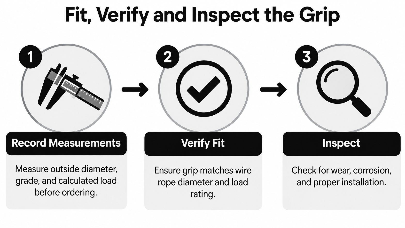
- Record the cable and design details before ordering. Measure the outside diameter with calipers on a straight, clean section. Note the grade and service load, then give those details to the supplier. A nominal spool size alone may not tell you whether the grip will seat correctly.
- Verify size and rating. Confirm that the measured diameter falls inside the grip's stated range. Check that the grip's working-load limit exceeds the service load multiplied by the project's safety factor. If either check fails, stop and choose a suitable termination.
- Prepare the rope end. Cut it square and secure or taper the end so the strands do not unravel while you handle the cable. A loose end can spread apart and make it harder to form a neat loop.
- Form the connection. Pass the cable through the anchor point and form the loop around the fitting or thimble. The loop or thimble should carry the load instead of letting the cable bear against a sharp edge.
- Orient the grip correctly. On a standard saddle-and-U-bolt clamp, place the U-bolt over the short dead tail and the saddle on the live, load-bearing rope. Reversing the parts reduces holding and can damage the rope. A missing thimble is another common mistake when the design calls for one.
- Tighten evenly. Bring the nuts down in stages and follow the manufacturer's torque instructions. Tighten until secure without crushing the strands. Uneven tightening can leave one side doing more of the work, while excess force can deform the rope.
- Load, recheck, and record. Bring the run to service tension, then inspect the grip after the assembly has settled. Record the torque and check that the grip has not moved. Repeat inspections on a planned schedule and note any change in tension, position, or condition.
A correctly installed railing cable should feel firm with slight flex, without sag or visible movement at the grip. Do not try to correct a broken wire by retightening the clamp; replace damaged rope. Inspect for discoloration, pitting, rust trails, and slippage, especially at the grip and where the cable leaves it.
For a complete railing kit, Ultra Modern Rails' standard cable is 5/32-inch 316 marine-grade stainless steel wire rope, and each kit includes 10% extra cable. All cable and hardware are 100% stainless steel. That material specification helps with corrosion resistance, while the safety of the connection still comes from the load path, the approved termination, and correct installation.
If you're planning a deck, balcony, or stair railing, bring your measured cable size and project layout to Ultra Modern Rails. The company supplies custom cable railing systems and can provide a free quote and drawing within 24 hours, helping you match the railing configuration to your space and installation needs.