

You've chosen the rail, matched the finish, and found a bracket that looks right in the product photo. Then the first hole exposes the problem: the wall is tiled, the cavity is insulated, or the visible cladding has nothing structural behind it. A railing can look perfectly aligned and still fail because the bracket is attached to the wrong layer.
Railing wall brackets are load-transfer components, not decorative spacers. The bracket, fasteners, substrate, and rail must work as one assembly. If any part of that load path is weak, a premium handrail won't make the installation safe or durable.
Table of Contents
- The Structural Role of Railing Wall Brackets
- Material Selection and Finish Durability
- Mounting Styles and Substrate Challenges
- Load Considerations and Code Compliance
- Choosing Brackets for Cable Railing Systems
- Troubleshooting Common Installation Mistakes
The Structural Role of Railing Wall Brackets
A railing wall bracket carries force through a defined load path. Pressure on the handrail enters the rail saddle, travels through the arm to the base plate, passes through the fasteners, and ends in the wall structure. That final connection determines whether the assembly remains stable. Studs, masonry, concrete, or engineered backing can carry the force, while drywall, thin cladding, and unsupported insulation cannot.
A bracket can look heavy and still be poorly supported. A thick arm fastened only to a finish layer has no dependable route into the building frame. The reverse also applies: a compact bracket anchored correctly into sound masonry may provide a stronger installation than a larger bracket fixed into a weak surface. Inspect the wall behind the visible finish before selecting hardware.
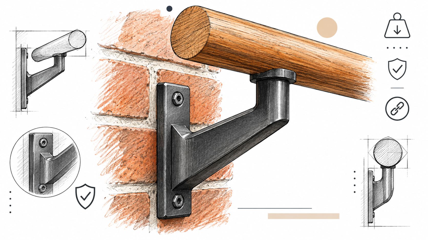
What the bracket actually does
Most railing wall brackets combine three working areas:
- Base plate: Bears against the wall and transfers force through the fasteners.
- Arm or standoff: Projects from the wall, creates hand clearance, and resists bending.
- Rail saddle: Supports the rail and holds its profile in the intended position.
The external design may be round, square, or minimalist. The structural question remains the same: can the complete bracket and anchorage keep the rail steady while delivering force into the substrate?
Geometry also affects everyday use. The standoff must provide a continuous, comfortable grip, and the saddle must match the rail's underside or connection detail. A square base does not prove compatibility with a square rail. Check the saddle dimensions, fastener layout, rail size, and available backing together.
Hidden wall conditions often control the installation. A stud may be offset from the planned bracket location, masonry may contain hollow sections, or a cladding cavity may require spacers and longer anchors. Confirm the substrate and anchor type before drilling, then verify that the fasteners develop strength in structural material rather than in the finish.
Practical rule: Choose the bracket and the anchorage as a pair. Approve neither until you know what the fasteners will actually engage.
The bracket is part of the safety-critical connection, so its arm geometry, base plate, fasteners, spacing, and backing deserve the same attention as the handrail. Detailed load values and jurisdiction-specific requirements belong in the code-compliance review, but the installation principle is straightforward: a strong rail cannot compensate for a broken load path.
Material Selection and Finish Durability
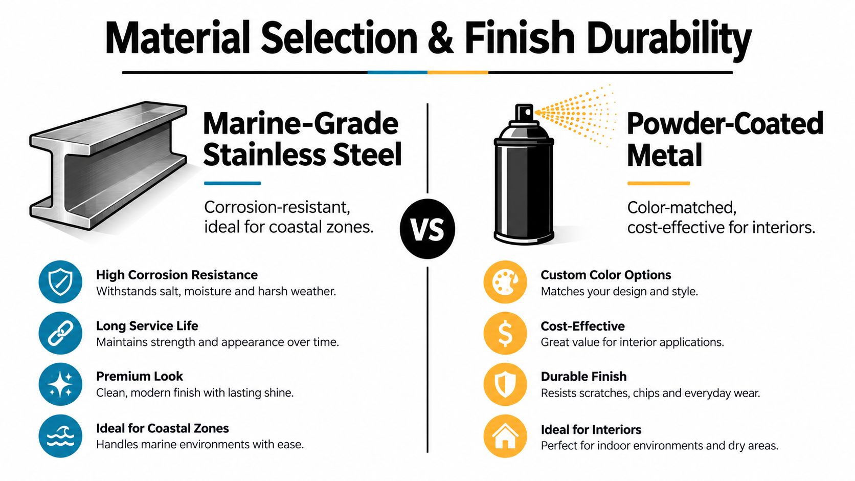
The right finish depends less on fashion than on exposure. A black powder-coated bracket may be entirely appropriate inside a conditioned home, while a coastal exterior can demand a corrosion-resistant stainless assembly. Matching the finish to the environment prevents a common failure pattern: attractive hardware that begins staining, bubbling, or rusting around the fasteners before the rail needs replacement.
Stainless steel for exposure
316 stainless steel is widely selected for outdoor and high-moisture applications because it offers stronger corrosion resistance than ordinary indoor-oriented metals. Marine-grade hardware makes particular sense near salt air, swimming pools, open balconies, and locations where condensation or frequent wetting is unavoidable.
Stainless steel still needs sensible care. Salt deposits and construction residue should be removed with a suitable cleaner, and abrasive tools can damage the surface. Do not treat the material as maintenance-free just because it resists corrosion. Regular visual checks around the base plate and fastener heads can catch staining or galvanic interaction before it becomes a structural concern.
The finish also has a design effect. Brushed stainless tends to show scratches and directional marks, while a polished surface highlights fingerprints and water spots. Those are aesthetic considerations, but they influence how often the owner will need to clean the system.
Painted and powder-coated metal
Painted or powder-coated steel offers strong visual control. A matte black bracket can disappear against a dark wall or create a deliberate contrast against pale finishes. It's often a practical choice for protected interior stairs, hallways, and conditioned commercial spaces where the hardware isn't exposed to persistent moisture.
The weak point is damage to the coating. A deep scratch, cut edge, or poorly sealed fastener opening can expose the underlying metal. Once corrosion begins beneath a coating, it may spread beyond the visible defect. Installers should handle finished components carefully, avoid dragging brackets across abrasive surfaces, and touch up damage with a compatible system rather than an unrelated household paint.
For a closer discussion of how stainless and steel behave in different environments, see this guide to stainless steel and steel corrosion.
| Exposure | Sensible bracket direction | Maintenance concern |
|---|---|---|
| Interior, dry and conditioned | Powder-coated metal or stainless steel | Protect the finish during installation |
| Humid interior or wet area | Corrosion-resistant stainless steel | Clean deposits and inspect fasteners |
| Exterior with weather exposure | Exterior-rated stainless steel or a properly specified coated system | Watch joints, scratches, and water traps |
| Coastal or salt-prone location | Marine-grade stainless steel | Remove salt residue and check dissimilar metals |
A finish can't compensate for poor installation. Even the most corrosion-resistant bracket may loosen if the fasteners are wrong, the wall is weak, or water enters an unsealed penetration.
Mounting Styles and Substrate Challenges
The wall finish is not the wall structure. That distinction controls the entire installation.
A surface-mounted bracket sits visibly against the finished face of the wall. It's usually easier to inspect and replace because the base plate remains accessible. A flush or concealed arrangement can produce a cleaner appearance, but it often leaves less room to correct uneven surfaces, hidden obstructions, or inaccurate backing assumptions. The visual preference should follow the structural condition, not override it.
Find the structure before drilling
Start with the wall investigation, especially in a retrofit. A stud finder can help on framed walls, but confirm the result with drawings, exploratory openings, or carefully placed pilot holes when the consequences of a wrong location are high. For masonry, identify whether you're drilling into solid brick, a mortar joint, hollow block, or a veneer system. Those materials don't provide identical anchor performance.
A reliable sequence looks like this:
- Map the finished layers. Record drywall, tile, stone, paneling, insulation, rainscreen, or other cladding between the bracket and the structural backing.
- Locate the backing. Identify studs, blocking, concrete, or solid brick rather than assuming the visible surface is structural.
- Select the fastener for that backing. Wood screws, masonry anchors, and concrete fasteners serve different substrates. A generic wall plug isn't a substitute for engineering.
- Check the bracket base. Confirm that the plate sits flat and that the selected fasteners fit its holes without forcing the bracket out of alignment.
- Seal exterior penetrations. Water entering around a fastener can damage framing and accelerate corrosion, even when the bracket itself is well made.
The different mounting types can help with the visual and installation distinction, but product instructions still govern the specific hardware. A bracket manual that says “mount to a stud” is not giving a casual preference. It's identifying the substrate needed for the load path.
Site observation: The bracket rarely fails first. The hidden wall condition, unsuitable anchor, or unsupported finish usually fails first.
This short installation video is useful for seeing how the bracket position, rail, and wall interface relate in practice.
Avoid fastening directly into cladding, tile, or drywall unless a tested system specifically permits it and provides the required backing method. Promenaid's installation instructions for wall-mounted railing systems likewise emphasize structural attachment and warn against treating cladding as the supporting member. If the wall has no accessible backing at the intended bracket locations, the correct fix may involve opening the wall, adding blocking, using an engineered standoff, or changing the mounting layout.
Load Considerations and Code Compliance
A railing wall bracket is part of the structural load path. Select it according to the force it must transfer into the wall, not by counting the screw holes in a catalog image. Modern handrail and guard systems are commonly designed for a 200-pound concentrated load and a 50 pounds per linear foot uniform load. Those forces travel through the rail, bracket, fasteners, backing, and wall structure. The National Laboratory handrail specification describes this complete attachment path rather than treating the bracket as an isolated spacer.
Spacing changes the demand on every connection. Wider spacing leaves fewer brackets carrying the rail, increases force at each attachment, and allows more movement between supports. Closer spacing can improve stiffness, but it cannot compensate for drywall, tile, cladding, or a weak anchor carrying the load instead of the structural backing.
The numbers need context
The commonly cited clearance rule requires 1.5 inches of minimum hand clearance between the handrail and adjacent wall. Accessibility and code guidance is summarized by NOMMA. Verify the finished condition, not just the bracket position. Trim, a thick base plate, or an oversized saddle can reduce the usable grip area and create a pinch point.
Guard requirements also change the design. Guards are generally required at open-sided walking surfaces more than 30 inches above grade. Common residential and commercial guard-height benchmarks include 36 inches and 42 inches, respectively, depending on the application and governing code. The IRC guard requirement reference shows why a bracket cannot be specified separately from the railing type and its location.
For jurisdiction-specific requirements, see our code and compliance guide. Check the IRC, IBC, accessibility provisions, and local amendments before finalizing the layout. Product approval documents and installation instructions still control where they impose more specific requirements.
Use this review before ordering or drilling:
- What system is being supported? A handrail, transition rail, guardrail, or cable assembly can impose different forces.
- Where does force enter the wall? Identify the framing, blocking, masonry, or approved anchorage behind the finish.
- What spacing does the tested system allow? Use the approved bracket and rail combination, not spacing borrowed from another product.
- Does the installed rail remain clear and grippable? Include trim, returns, joints, and the actual bracket profile.
- Which jurisdiction governs? Confirm the adopted code and any local amendments.
Approval data also shows why generic spacing advice can fail. One approved bracket series lists allowable loads from 250 to 392 pounds, with maximum spacing from 5 feet on center to 7 feet 10 inches on center. Separate approval data limits one wall-mount arrangement to 1.37 kN, or 308 pounds, vertically downward, while a post-to-fascia arrangement carrying the same continuous rail load is rated at 2.74 kN, or 617 pounds. The FHC railing approval documentation ties those values to tested configurations. Do not transfer a rating to a different substrate, anchor pattern, spacing, or rail layout without verification.
Choosing Brackets for Cable Railing Systems
Cable railing adds a second structural conversation. The cables are tensioned between posts or end fittings, while the handrail still needs to remain stable for a person using it. A wall bracket may therefore experience a combination of downward, lateral, and local forces near cable terminations, corners, transitions, and rail ends.
The clean appearance of cable railing can hide those concentrated demands. A long, uninterrupted handrail may look light, but its ends and turns often deserve more attention than the middle of a straight run. At those locations, cable tension changes direction or terminates, and the connection must prevent the rail from twisting, lifting, or pulling away from the wall.
Treat ends and turns as special zones
Don't distribute brackets by distance alone. Review the layout around:
- Cable end fittings, where tension enters the rail or adjacent structure.
- Corners and direction changes, where the rail and cable geometry introduce additional movement.
- Rail terminations, where the last bracket and fastener group resist local rotation.
- Transitions to posts, where the load path changes from a wall mount to a post-supported condition.
- Stair slopes, where bracket orientation and hand clearance must follow the actual rail angle.
Independent approval data shows that moving load transfer from wall mounts to post-to-fascia brackets can substantially change allowable vertical capacity, with one documented comparison rising from 308 pounds to 617 pounds in the tested arrangements. The lesson isn't to substitute posts automatically. It's to recognize that the support condition controls capacity, especially where a cable system concentrates force.
A wall bracket for cable railing should match the rail profile and the cable hardware without creating interference. The saddle needs enough bearing area to prevent point loading, while the standoff must preserve the required grip clearance. If the bracket forces the rail into an awkward position, the installer may compensate by bending hardware, shifting fasteners, or reducing clearance. Those shortcuts create a visually neat problem and a structural one.
Coordinate the kit before installation
Select the rail, brackets, cable fittings, and substrate anchors as one specification. Confirm that the bracket is approved or documented for the intended rail material and loading arrangement, and don't assume a bracket supplied for a decorative handrail is suitable for a tensioned cable system.
For a modern black-metal system with a wood top, Ultra Modern Rails supplies custom cable railing sections and hardware for interior and exterior applications. Treat that type of product as a complete system during planning. Confirm section lengths, stair conditions, handrail details, mounting surfaces, and local code requirements before ordering or drilling.
The most reliable installation keeps cable tension out of the wall bracket whenever the design allows the posts and end fittings to carry it. Where the wall bracket is part of the cable load path, have the manufacturer or qualified designer verify the fastening and spacing rather than relying on appearance or a generic hardware chart.
Troubleshooting Common Installation Mistakes
Most railing problems announce themselves before final completion. A bracket rocks when pressed, the rail develops a visible dip, or the cable system loses tension after the first adjustment. Those symptoms point to a load-path problem, not merely a cosmetic defect.
Bracket pull-out
A bracket that pulls away from the wall usually has one of three causes: the fastener missed the structural member, the anchor doesn't suit the substrate, or the finish layer was mistaken for backing. Remove the trim cover if possible and inspect the fastener engagement. On a framed wall, verify that the screw reaches the stud or installed blocking. On masonry, confirm the anchor type and the actual material behind the drill point.
Don't solve movement by tightening harder. Over-tightening can crush a finish, strip the substrate, or distort a thin base plate. Replace unsuitable fasteners and correct the backing instead.
Rail sagging
Sag can result from excessive bracket spacing, an undersized rail, a loose saddle connection, or a bracket arm that is bending under load. Check the rail with a level, then inspect each saddle and base plate. If the supports are sound but the span remains flexible, the remedy may be a closer support arrangement or a different rail profile, subject to the system documentation.
A manufacturer's tested spacing is more useful than an informal rule copied from another project. Product guidance cited in the trade literature commonly places bracket spacing in a range such as 32 to 48 inches, but the applicable value depends on the system, substrate, rail, and approval. The Fine Homebuilding guidance on railing installation reinforces the need to evaluate exact placement and structural attachment rather than treating spacing as a universal constant.
Cable tension loss
If a cable loosens after tensioning, inspect the end termination before adjusting every cable again. Look for slippage, a poorly seated fitting, movement at the post, or a handrail that shifts under the cable force. Re-tensioning without correcting the moving component only masks the cause.
Use this final inspection sequence:
- Press each bracket by hand. Movement at the base plate requires correction.
- Check every fastener. Confirm engagement in the intended stud, blocking, concrete, or masonry.
- Inspect the rail connection. Make sure the saddle supports the profile without rocking.
- Measure clearances and height. Check the finished assembly against the governing code and manufacturer instructions.
- Review ends and corners. These locations often need more support than a straight middle span.
- Tension cables gradually. Stop if the rail twists, lifts, or pulls the brackets out of alignment.
A clean installation is not finished when the last screw is driven. It's finished when the wall, fasteners, brackets, rail, and cable hardware behave as one stable assembly.
Ultra Modern Rails provides factory-direct modern cable railing systems, custom sections, stainless steel cable and hardware, and support with drawings and quotes for residential and commercial projects. Visit Ultra Modern Rails to review mounting options and request a system that accounts for your rail layout, finish, and actual substrate conditions.