

You've just tensioned the last run on a new deck. The cables look straight, the posts feel solid when you push them, and the top rail sits clean. Then a building inspector, or a careful homeowner with a test sphere, presses between two cables at mid-span and the opening grows. That moment is where a tension cable kit stops being a hardware purchase and becomes a structural system you either verified or guessed at.
Table of Contents
- Why a Tension Cable Kit Deserves System-Level Thinking
- Measuring, Planning, and Choosing Hardware Before You Order
- Tools and Hardware You Actually Need on Site
- Installing Posts, Routing Cables, and Sequencing Tensioning
- Verifying Tension, Deflection, and Code Compliance
- Maintenance, Corrosion Control, and Inspection by Environment
- Troubleshooting Common Problems and Final Field Checklist
Why a Tension Cable Kit Deserves System-Level Thinking
I have been called to decks where every cable rang tight when plucked and the job still needed rework. The end posts had pulled slightly inward, one long run deflected more than the short run beside it, and the middle cables carried noticeably different tension from the top and bottom runs. Nothing looked broken. The assembly tension cable kit system had not been installed as a coordinated unit, so appearance hid the compliance problem.
A spool of cable and a bag of fittings don't make a guard. The guard is the cable, terminals, posts, anchors, blocking, framing, and top rail working together under load. If an end post flexes, tension you set in the morning isn't the tension you have after the next run is pulled up. If a corner is weak, two directions of load will find that weakness faster than any single straight run.
Three Principles That Run the Whole Job
- Tension is a system property: One cable can't be judged alone, because tightening it changes post position and affects its neighbors.
- Anchoring matters as much as cable strength: Strong cable attached to inadequate framing is still an inadequate guard.
- Compliance is measured, not seen: Parallel lines can conceal uneven tension, excessive deflection, and openings that enlarge under pressure.
That is why good installers treat the work as a controlled load-and-inspection process. You plan the load path before you order, you stage the hardware before you drill, you tension in sequence, and you verify with measurements after the system settles. The wrench is only one step.
Tight by feel tells you a cable resists your hand. It doesn't tell you what the opening does under load, what the post is doing, or whether the next run will match.
Leave behind the idea that tighter is always better. A cable can be under-tensioned and allow too much deflection, or over-tensioned until posts bend and terminals suffer. The target is even, specified tension in a structure stiff enough to hold it, verified at the openings that matter. Get that mental model right and the rest of the work becomes a sequence of checkable decisions instead of hopeful tightening.
Measuring, Planning, and Choosing Hardware Before You Order
A measured layout keeps ordering decisions tied to the actual load path. On a stair landing, for example, a corner post may carry tension from two runs, while a gate opening breaks the cable line entirely. Measure each deck or stair side separately, record post-center distances, and mark corners, gates, stair transitions, and every point where a cable must terminate. A perimeter total alone will not show where those loads collect.
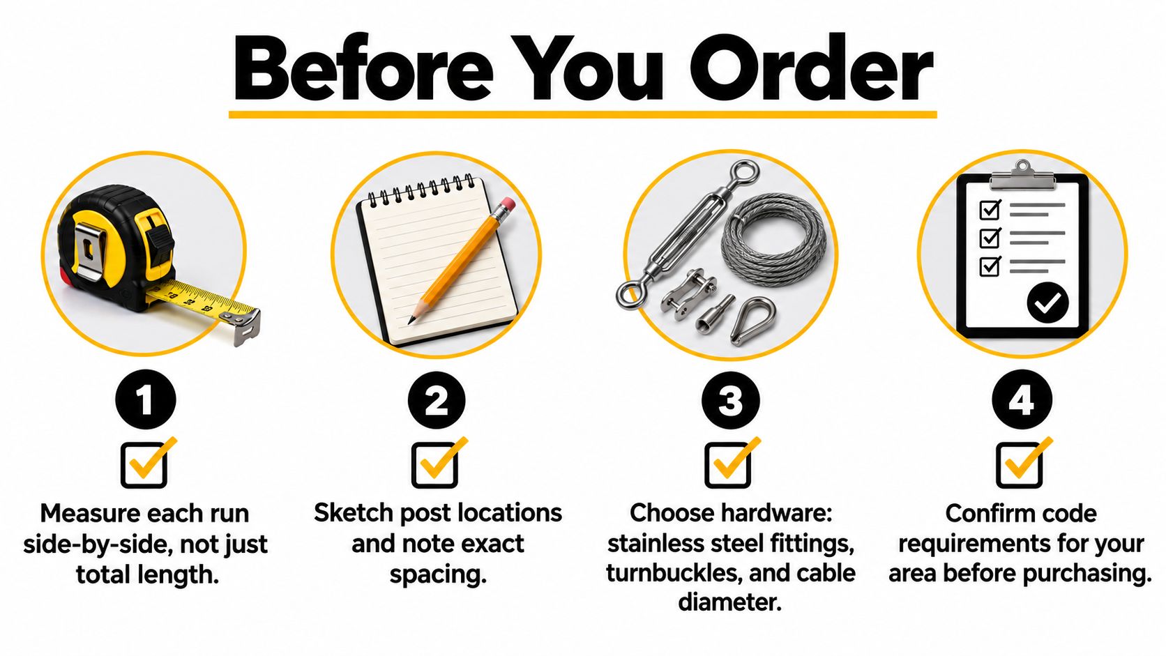
Set the infill layout before selecting fittings. The 2015 IBC and IRC require guard infill to prevent a 4.0-inch-diameter sphere from passing through. The Ultra-Tec engineering data for cable guard infill gives engineering guidance using an 8.7-pound test force and describes typical layouts with 1/8-inch, 1x19 stainless cable, spaced roughly 3.125 inches on center, with unsupported spans up to 48 inches. Treat those dimensions as a design reference, then confirm the local code edition and amendments before ordering.
Use the drawing to check how the system will behave, not just how many feet of cable it needs. Longer unsupported spans allow more deflection; adding intermediate posts reduces span but adds posts and terminals. Review railing post spacing for cable systems as you place supports, and confirm that the selected layout works with the cable system's limits.
Before ordering, resolve the details that affect cumulative post load and hardware count:
- Mounting method: Deck mounting and side mounting transfer anchor loads differently. Verify blocking, rim material, and access for the chosen fasteners.
- Corners and stairs: Decide whether corner posts terminate separate runs or allow cable through an angled transition. This determines terminal requirements and how loads meet at the post.
- Kit length: For standard-length kits, round up for each measured side. Do not order to an exact cut based on dimensions that have not been checked on site.
Call the building department to confirm which code edition and local amendments apply to horizontal cable infill, and what documentation the inspector expects at final inspection. A compliant-looking layout is not proof of compliance; the installed opening and supporting structure still need to meet the applicable requirements.
Bring in a structural designer before ordering if end posts bear on questionable framing, the guard is commercial, or anchors need blocking that is not present. Reinforcement is simpler to plan before drilling. A kit matched to a measured, reviewed layout arrives ready to build; one chosen from a rough perimeter measurement can leave gaps in both hardware and support.
Tools and Hardware You Actually Need on Site
Stage the job like a pre-flight check. Lay out cable, terminals, and tools by run, not in one mixed pile, so a missing fitting shows up before you have drilled posts waiting. Count tensioning ends and fixed ends separately. Confirm every cable run has the terminal type the manufacturer specifies for its post material and thickness.
The Kit Itself
You need cable of the specified construction and diameter, terminals matched to that cable, and enough spare material to remake a bad cut without stopping the job. Swaged fittings give a clean, factory-consistent termination when they're applied with the correct die and press. Mechanical fittings trade a bulkier profile for field adjustability and the ability to release and reset a cable. Either works when it's installed to spec. Either fails when it's mixed with cable or tooling it wasn't designed for.
Don't judge a kit by breaking strength alone. Wire-rope standardization dates to June 1, 1925, when the U.S. Federal Specifications Board set a factor of safety of 4.5 for tabulated safe loads, showing that allowable service load, not breaking strength, determines suitability, as documented in the 1925 federal wire-rope specification. Fittings, anchors, posts, span, and installation quality all sit between a catalog strength number and a guard you can trust.
Cutting, Tensioning, and Fastening Tools
- Wire rope cutter: A proper cutter made for stainless cable, not bolt cutters or an abrasive wheel that frays and heat-discolors strands.
- Swaging or tensioning equipment: The press, driver, or calibrated tensioning device your fitting system requires, with the correct dies or keys.
- Torque wrench: Matched to the fastener values in the instructions, because anchor and clip torque aren't feel-based numbers.
- Drill bits and templates: Sharp bits sized for pass-through and terminal holes, plus a post template so spacing stays consistent from post to post.
Add the quiet essentials. You'll want a tape, level, cable grips or a lacing tool for feeding long runs, post protectors or sleeves where cable passes through intermediate posts, isolators where dissimilar metals meet, and caps for exposed terminal ends. Systems such as those from Ultra Modern Rails combine stainless cable and hardware in factory-configured sections, which reduces mismatched parts, but you still verify counts against your layout.
What you don't need is a bigger wrench to compensate for missing measurement tools. If you can't cut cleanly, tension repeatably, and torque fasteners to spec, you're not ready to start. That's not gatekeeping. It's the difference between an install you can verify and one you can only describe.
Installing Posts, Routing Cables, and Sequencing Tensioning
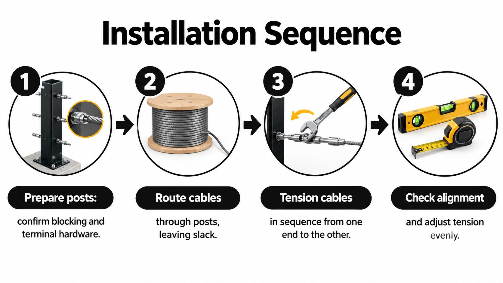
Start with the structure, because cables will faithfully pull on whatever you give them. Confirm blocking under deck-mounted posts and solid framing behind side-mounted brackets. Set each post plumb, align the cable plane across the run, and fasten anchors to the manufacturer's torque values. Recheck plumb after fastening, since tightening one side of a base plate can walk a post out of position.
This sequence graphic lays out the order that keeps the work controlled from post prep through final adjustment.
Routing Without Damage
Uncoil cable in large loops and never pull a kink straight and hope it disappears. A kinked or burred section is weakened and won't seat properly in a terminal, so cut it out. Feed cable through intermediate posts with a lacing tool or guide so strands don't catch on hole edges, and use protective sleeves where the system calls for them. Keep bends gradual, especially at stair transitions and corners.
Corners deserve their own plan. Using a corner post as a termination point for both runs keeps tension independent and makes future adjustment simpler. Passing cable around an angled transition reduces terminal count but demands hardware rated for that angle and a post stiff enough for combined load. Pick one approach per corner and stick to the hardware list it requires. Improvising a corner with straight-run fittings is a reliable way to build in uneven tension.
Sequencing the Tension
Seat all cables loosely before tensioning any of them fully. Then work from the center cable outward, or follow the sequence your system engineer specifies, taking small increments and alternating sides of a run. Bring the whole panel up gradually. If you fully tension the top cable first, the post moves, and every cable below it starts from a changed geometry.
Watch the posts while you work. A post head that creeps inward as you add cables is telling you the anchorage or framing is reaching its limit. Stop and fix the structure instead of distributing the problem across more cables. On stairs, tension in the same progressive pattern, and keep the rake of the cables consistent with the handrail line before final tightening.
The clip discipline from wire-rope work applies directly here. OSHA guidance requires clips and fastenings to follow manufacturer or qualified-person instructions, with even tightening to specified torque, retightening after initial load, and periodic inspection, and it specifies that U-bolt clips go with the U section on the dead end of the rope rather than guessed spacing or torque, per OSHA guidance on safe wire-rope sling use. Where your kit uses set screws, swages, or threaded terminals instead, the principle is identical. The specified method is the method.
This install video shows the physical rhythm of routing and progressive tensioning before you apply it to your own runs.
After the first full loading, go back over every connection. Cable under tension can reduce slightly in diameter and fittings can settle, so retightening after the initial load isn't a correction, it's part of the sequence. Note which terminals moved and how much adjustment remains. A tension cable kit installed this way can be paused, handed to another installer, and resumed without anyone guessing where the load stands.
Verifying Tension, Deflection, and Code Compliance
At final inspection, the cables can look evenly tensioned while the end posts are carrying too much load. Roughly 200 to 240 lb of tension per strand adds up quickly: an 11-cable, 36-inch guard can impose approximately 2,640 lb on its end supports. That cumulative force makes post stiffness and anchorage central to whether the assembly passes inspection, as explained in the continuing-education course on cable railing systems. Each added cable loads the same end posts.
More tension does not mean a safer rail. Exceeding the specified range can pull posts inward, change end spacing, and strain terminals. The cable may still deflect too far at mid-span. Check the complete run under its intended tension, not just how tight it feels at one point.
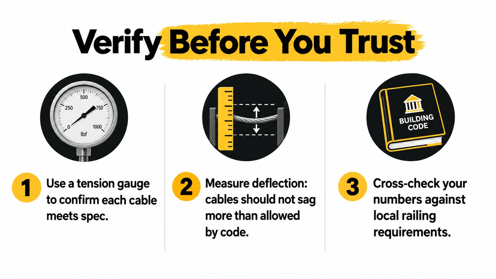
Verification is a set of recorded observations, not a final glance. Check openings along the whole run, including beside terminals and corners, then apply the required sphere check at mid-span, near intermediate posts, and at corners. Deflection can vary from one point to another. Compare end and corner posts with their pre-tension readings, and stop to investigate inward movement before applying more tension.
Retest after initial loading and after a temperature swing, since both can change cable behavior. Where the manufacturer specifies a measurement method, use it rather than judging tension by thumb pressure. A cable tension gauge for railing work provides a way to make readings repeatable. Two cables may feel alike but carry different tension; hand pressure also leaves no record for an inspector.
Field standard: Record the tension setting, sphere-test result, and post condition for each run. If those details are missing, the run has been inspected visually, not verified.
For commercial and public projects, retain installation records and obtain approval from the authority having jurisdiction. If a run passes only after over-tensioning, get a structural review instead of applying more force. An added intermediate post or improved blocking may be the appropriate fix. A compliant tension cable kit passes the sphere test at specified tension, with posts remaining straight and adjustment available. If the installation relies on brute force to pass on the day, it is carrying a problem into service.
Maintenance, Corrosion Control, and Inspection by Environment
A cable run can look clean while corrosion starts under a fitting or where water sits against a post. Stainless cable needs routine care, and the inspection interval should suit the exposure. Specify and inspect the full system: cable, terminals, posts, fasteners, and isolators must work together for the site's loads and applicable codes. The New York State DOT cable infill specification reflects that system-level approach. Stainless hardware alone does not make an assembly suitable for a marine environment.
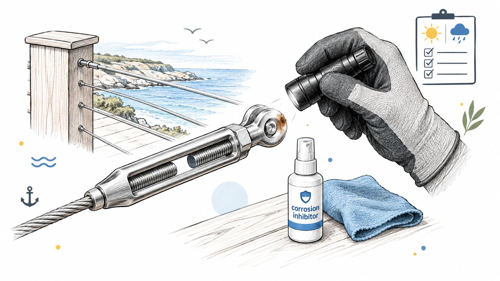
At each inspection, check areas that collect moisture or carry load, not only the exposed cable. Adjust the cleaning routine to the site:
- Inland and dry: Rinse off dust and pollen periodically, wash with mild soap when film builds up, and check terminals and cable condition during regular seasonal inspections.
- Humid urban: Pollution film and trapped moisture can stain surfaces sooner. Wash more often, clear debris around post bases, and inspect pass-through holes where grime rests against the cable.
- Salt air: Rinse with fresh water frequently to remove salt deposits, which can hold moisture against fittings. Inspect terminals and fasteners directly.
- Splash zone and pool adjacent: Chlorides, standing water, and mixed metals make this an aggressive exposure. Check drainage and isolators closely, and rinse regularly.
Look beneath bottom rails and around post bases for trapped water. Inspect swage areas for cracks or slippage, and pass-throughs for abrasion. Early pitting may appear cosmetic, but can signal localized corrosion. Orange staining may come from iron particles left by nearby grinding or cutting rather than damage to the cable itself. The guide to stainless steel and steel corrosion in railing systems explains how contact between these materials can affect railing components.
Match the repair to the source. Fit isolators or gaskets between dissimilar metals, clear blocked drainage, and replace fittings with pitting at a load-bearing crevice rather than polishing over the damage. Avoid steel wool and carbon-steel brushes on stainless steel; they can leave particles that stain the surface. A tension cable kit specified for its exposure and maintained to suit that environment is more likely to retain both its finish and its intended tension. “Maintenance-free” is not a field condition.
Troubleshooting Common Problems and Final Field Checklist
Most callbacks follow a short list of causes. A practical commissioning record should document cable identification, terminal type, torque or tension setting, post deflection, and inspection date, and the common field failure modes are uneven tension, over-tensioning that bends posts, under-tensioning that allows excessive deflection, and failure to retighten after initial load, as summarized in the overview of cable railing practice. Work the symptom back to which of those you're seeing.
Symptom, Cause, and Fix
- Cables look wavy across a panel: Tension was taken up one side at a time. Back the run off evenly and retension in small increments from the center outward.
- Post head leans inward: Cumulative load exceeds what the anchorage or framing holds. Reduce tension to spec, add blocking or reinforcement, and retension only after the post stands plumb under load.
- Visible sag at mid-span: Under-tensioning, an over-long unsupported span, or both. Tension to spec first, and if deflection still fails the sphere check, add intermediate support instead of over-tightening.
- One cable loosens repeatedly: A settling terminal, incorrect clip orientation, or a fitting that was never retorqued after first load. Inspect the termination, correct orientation, and reset it to the specified method.
- Staining after nearby construction: Mortar splash or grinder dust contaminated the surface. Clean promptly with stainless-safe methods and protect finished runs during remaining trades work.
Know which fixes stay local. A single damaged terminal can be replaced and that cable reset to match its neighbors. Uneven tension across a panel, a moved post, or a span change means retensioning the whole run, because one cable's setting only makes sense relative to the others.
Close every job with the same written pass. Record each run's cable and terminal type, final torque or tension setting, post deflection reading, sphere-test result by location, and the inspection date. Add a note for the first retensioning visit after initial use, and tell the owner plainly that this visit is scheduled maintenance, not a repair. Owners who expect it don't panic when cables settle, and installers who document it don't argue from memory months later.
Print that checklist and walk the deck with it. A tension cable kit finished this way leaves behind evidence, not impressions, and that's what separates a lasting install from a callback.
If you're planning a deck or stair guard and want sections configured around your actual post layout, spans, and mounting conditions, Ultra Modern Rails supplies custom stainless cable railing systems with a free quote and drawing so you can verify hardware and spacing before you order. Bring your measurements, corner conditions, and local code answers, and specify the kit as the complete system this guide describes.